Manufacturers of thermal mass flowmeters for gases provide different ways for users to obtain flow meter diagnostics. Understanding the diagnostics is important because it helps users maintain the meter’s accuracy, reliability, and performance. Some new direct communication methods to access the configuration software offer unique benefits to meter users. In this article, we explore how users can obtain diagnostics (highlighting recent advancements), maximize the benefits of configuration software, and reveal its most common uses and impact on the meter while still in the field.
Four Ways to Access Flowmeter Diagnostics
- Push Buttons
The most common method to access diagnostics is to use push buttons on the faceplate of a thermal mass flowmeter or its display - Configuration Software
Some manufacturers have configuration software that the user downloads to a laptop. This software often has a nominal charge or is included with the purchase of a meter. In this case, the user will attach an interconnecting cable between the flow meter that terminates at one of the computer’s USB ports. - SCADA System or PLC
Assuming the flow meter has communication outputs, such as Modbus, PROFIBUS, or BACnet protocols, the user can then access menus of the flow meter within their SCADA system or PLC. The menus provide the ability to make configuration changes on the meter or conduct diagnostics.
Some meter users require HART Communication, and their control systems are accessing the data off of the 4 to 20 mA terminals rather than the communication terminals.
A few flowmeter manufacturers provide a SIL2 rating, enabling a way to verify proper flowmeter operation via the analog output (e.g., readings below 4 mA or above 20 mA would generally represent faults that are detected by the user’s control system). - Direct Access Communication
Recent advancements exist in communicating between a laptop and the meter when accessing configuration software. One manufacturer has integrated a separate communication port built into the meter, providing a second communication channel off of a mini-USB connector in addition to the PLC or SCADA system communication outputs. This option prevents conflicts between the network data being transmitted and the data acquisition and control system.
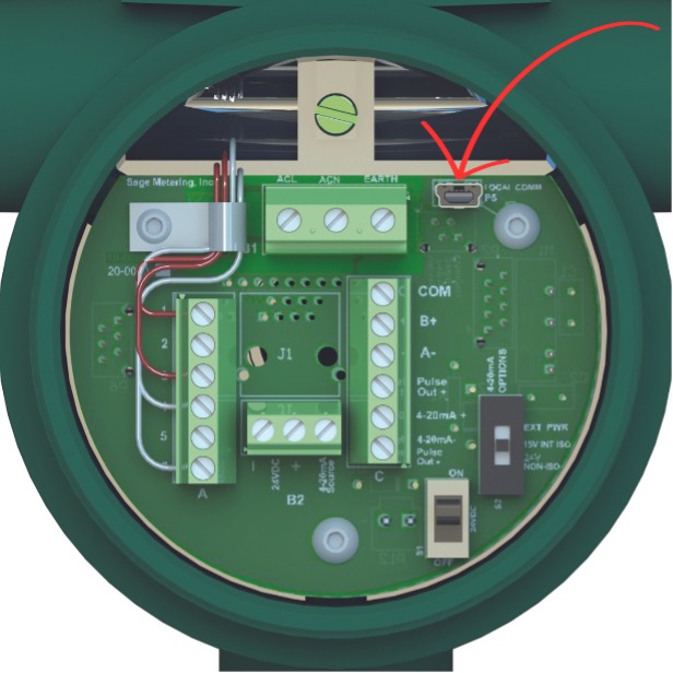
One benefit of this system is that the configuration changes or diagnostic procedures can access one of the meters within a network without interfering with the other meters. In other words, the network is not broken or interrupted, ensuring that the control systems do not lose the data coming from the other flow meters during this operation.
Taking this a step further, the same manufacturer offers a Bluetooth communication option between the gas flowmeter and the laptop. Bluetooth enables the user to connect with the meter remotely without having to connect to the laptop physically. This strategy provides enormous advantages, especially when verifying operation or reconfiguring a flow meter that is out of reach (e.g., high up on a pipe or perhaps in an oil well in a muddy field).
Additionally, we offer Ethernet outputs, along with a few other manufacturers, which provide additional benefits and functionality.
The Benefits of Configuration Software
When a thermal mass flowmeter is manufactured, it is produced to the specific parameters of the order. However, in some cases, the parameters provided are incorrect, or it may be discovered after the installation of the flow meter that the process conditions have changed. The user then needs to correct for these changes, or the meter won’t be accurate, and adjustments using configuration software makes it easy to do so in most cases.
Some manufacturers’ configuration software provides diagnostics for self-checks for the user to verify that the meter’s sensor is clean and accurate and that the meter is within calibration. Depending on the manufacturer’s meter and software, this can be accomplished with the meter in the field without removing it from the pipe. These self-check procedures avoid the expense of uninstalling and returning the meter for factory modifications or recalibration, as well as the associated labor to uninstall and later reinstall the meter.
The benefits of such software are saving time and money and verifying the meter’s accuracy.
6 Common Reasons to Access the Configuration Software
1. Underestimated Full-Scale Flow Rate
What if a user underestimated their full-scale flow rate? For example, they may specify 200 SCFM (standard cubic feet per minute) of natural gas for their boiler flow, only to realize upon installing the meter that the flow often pegs at 200 SCFM but does not go any higher. In this case, they can reset the full-scale flow rate within the meter to, let’s say, 250 SCFM. This reconfiguration would thus be important; otherwise, the totalizer on the meter would under-report. In other words, every time the flow exceeded 200 SCFM, the totalizer would not have counted it. However, once the software is accessed to update the full scale, the flow meter will take on the new setting and be able to reach 250 SCFM (and 20 mA will now report as 250 SCFM).
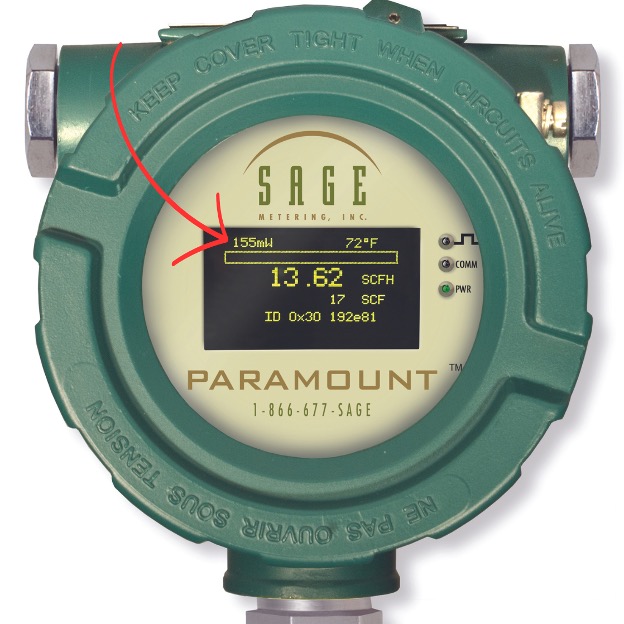
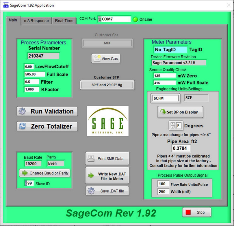
Note, in the above example, a change as small as 50 SCFM out of 250 SCFM will have minimal impact on the flow meter’s calibrated accuracy since most manufacturers take data about 20% above the actual required full scale. For those manufacturers who don’t do so, the internal math will simply extrapolate to the higher value. Furthermore, some manufacturers can guide the user on what the magnitude of the change should be (either from boiler ratings in BTU which can convert to SCFH, or from knowledge of the relationship between pressure and flow rate). At my company, we offer the raw meter output in mW (milliwatts) directly on the left upper corner of the display (see figure 2), and that value continues to increase beyond the full scale. Thus, the user could report the max mW observed, and we will advise what SCFM value corresponds to that reading.
2. Wrong Schedule Pipe
What if a user ordered an insertion-style meter for a 4” Schedule 40 pipe, then realized that the actual pipe is Schedule 80? Since the smaller diameter of the thicker pipe will result in an over-reporting of approximately 10%, changing the pipe schedule in the configuration software will remedy the concern. Changing pipe schedules on large pipe sizes (e.g., above 4”) is perfectly acceptable. Caution, however, when changing to smaller pipe sizes (below 4”), non-linear relationships will occur, which will affect accuracy.
3. The Gas Mixture Changed
What if the gas mixture changed from the factory-requested calibration mix? That, too, can be remedied through the software.
4. Setting a Low Flow Cut Off
Thermal mass flow meters are extremely sensitive, and a low flow cutoff may be needed even when the compressor or gas supply is off. Since long pipe runs may have some turbulence, the flow rate may be reading slightly above zero just from the free convection within the pipe. The remedy is simply setting a low flow cutoff slightly above the unwanted readings using the software. Accordingly, the totalizer no longer reads unwanted heat transfer (otherwise, the monthly gas consumption readings would over-report).
5. Miscellaneous Adjustments
Some less common adjustments may include changing decimal points for additional resolution; slowing the response time of the flow output due to choppiness coming from a compressor or upstream fan; or even changing the baud rate in a Modbus application.
6. Diagnostics
As previously noted, the most common reason for accessing the software is diagnostics. Most manufacturers at least offer self-checks for basic functionality or electrical checks to ensure that all the meter’s sub-systems perform correctly.
Some manufacturers offer in-situ calibration checks built into the software that allows the user to verify that the meter remains in calibration to ensure there has been no drift or shift in the flow meter since its original NIST calibration. This is a very powerful diagnostic since it essentially checks operation, including the condition of the active element (the sensor). It will not pass the test if the calibration has changed or the sensor has become fouled.
The software may generate a printed Pass or Fail report for auditors or ISO compliance. Additionally, some software programs, such as ours, offer data logging to report the actual flow rate over time.
In-situ calibration is powerful since it eliminates the need to return the flowmeter for annual calibration verification, removing the expense of uninstalling and reinstalling the meter in the field. It also allows the user to build confidence in the accuracy of their flow meter in critical applications such as combustion control, environmental compliance, or process efficiency and throughput.
In Summary

Manufacturers integrate various ways to access diagnostics for thermal mass flowmeters. Some new direct communication methods through a dedicated meter port prevent conflicts between the data and the control system and permit diagnostic procedures on a single meter without disconnecting the network (of meters) or interfering with performance. Other breakthroughs, such as Bluetooth and Ethernet, provide additional benefits.
Ultimately, some manufacturers’ thermal mass flowmeter configuration software saves time and money by permitting users to run electrical performance checks, calibration checks, and changes to configurations such as full scale, engineering units, gas mix, and other specified parameters.
Bob Steinberg is the founder, president, and CEO of Sage Metering. He has over 40 years of instrumentation experience. Before forming Sage Metering in 2002, Steinberg managed thermal mass flowmeter sales at Kurz Instruments, Sierra Instruments, and Eldridge Products. While at Weston Instruments, he was a product marketing engineer. He has a BSEE and a BA from Rutgers University. Bob Steinberg is the author of The Triple Play of Business: A Strategy for a Healthy Company. More information on Bob and his company can be found at SageMetering.com.
Source of Article