Unlike traditional insert sensors, external sensors do not require pipes to be cut or operations to be halted in order to complete the installation process; instead, the sensors are mounted on the exterior of the pipe and measure flow by transmitting acoustic signals into the pipe wall before entering the fluid.
The question may arise as to how well a meter can perform if its sensors never make contact with the medium flowing inside the pipe. But the fact is, clamp-on ultrasonic flow meters can demonstrate a very high level of accuracy and reliability that is on par with or even better than other flow measurement technologies. The key to determining whether this type of flow meter lives up to its potential lies in properly matching the sensors to the pipe being measured.
Given that clamp-on meters are capable of measuring flow within pipes of varying diameters, materials and wall thicknesses, it is imperative for suppliers to offer a suitably broad range of clamp-on Lamb wave sensors with differing frequencies. This will help customers to achieve the best possible match between the sensors and the resonant frequency of the pipe wall, ultimately resulting in more accurate flow measurement.
Shear mode vs. Lamb wave sensors
To explain why it is so important to match the external sensors to the pipe being measured, it is first necessary to distinguish between two different types of sensors that can be utilized by clamp-on ultrasonic flow meters: shear mode and Lamb wave.
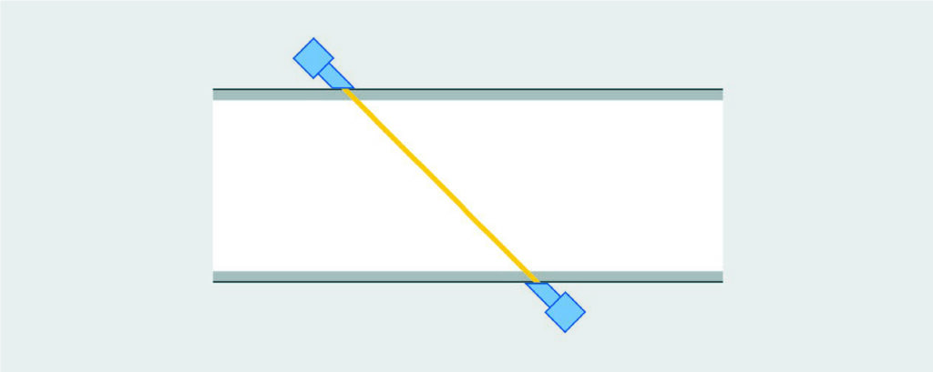
Shear mode or narrow beam sensors are the most common type used in clamp-on flow measurement and demonstrate reasonably good performance within a limited range of process conditions. Shear mode sensors inject an acoustic signal into the pipe wall, effectively forcing the signal through the pipe and into the opposing sensor (Figure 1). Although this technology is easier and less expensive to employ than Lamb wave sensors, it is sensitive to suspended solids and bubbles exceeding a few percent by volume. This can lead to poor performance or even complete loss of the receive signal. Shear mode sensors are most suitable for flow surveys and check metering applications requiring the use of a portable flow meter kit, which is not generally designed to carry a large selection of sensors. However, for the majority of dedicated metering applications, it is preferable to use Lamb wave technology for better accuracy over a wider range of liquid conditions.
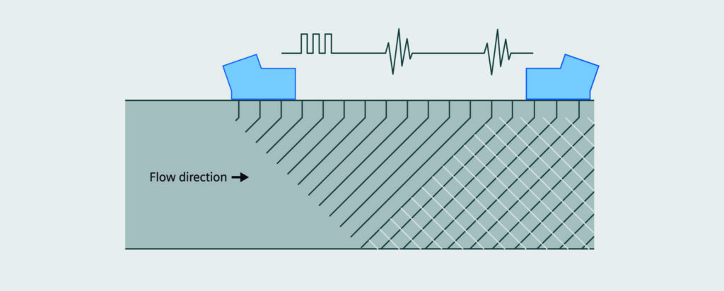
Lamb wave or wide beam sensors operate by broadcasting various frequencies through the pipe in order to locate the frequency most closely matched to that of the pipe wall. This frequency is transmitted into the flowing media with the pipe wall acting as a waveguide (Figure 2). This method employs a lower transmit voltage (approximately 30 volts) and produces a particularly strong and focused signal covering a large axial area of the pipes inside diameter. This results in a much higher signal amplitude than is the case for the shear mode. In addition, the wider beam offers formidable resistance against the effects of suspended solids and bubbles. Therefore, there would have to be a significantly higher concentration of interfering particles to disturb the beam and cause signal loss, making Lamb wave sensors ideal for applications containing up to 15 percent suspended solids or bubbles. They are designed primarily for steel pipes and are the preferred sensor type for hydrocarbon and gas applications. This method does, however, require a wider range of sensors to be made available due to its dependency on the resonant frequency of the pipe wall, a relationship that will be more closely examined in the following sections.
Flow meter suppliers limit sensor choices
Clamp-on ultrasonic flow meter suppliers, including at least one major corporation with global customer reach, have publicly acknowledged in marketing literature and academic papers the importance of offering a variety of Lamb wave sensor frequencies for optimal flow measurement results. Nevertheless, the vast majority of these suppliers do not support this concept through their product lines. Most companies produce a limited selection of Lamb wave sensors, presumably under the belief that these are enough to ensure customer satisfaction without leading to confusion over which sensor should be selected.
In contrast, Siemens has chosen to make a wide range of Lamb wave sensors available to help pipeline operators attain the strongest possible signal and highest level of measurement accuracy. In fact, the Siemens 1011 High Precision WideBeam Sensor line is available with a total of 12 different clamp-on Lamb wave sensors for liquid applications and an additional 9 for gas applications – a larger selection than what is offered by any other flow meter supplier. These sensors vary both in physical size and frequency range. To eliminate the possibility of an incorrect selection, Siemens publishes comprehensive selection guidelines and provides worldwide customer support staffed by experts in clamp-on ultrasonic flow.
Why variety is key
Siemens’ decision to offer a larger number of Lamb wave sensors than its competitors is based on well-established scientific principles related to Lamb or plate wave behavior. Lamb waves represent a complex form of acoustic wave propagation in a plate, in which the wave velocity depends on the relationship between the plate thickness and wavelength.
Siemens High Precision Sensors are designed to excite a specific mode of Lamb wave within a bounded pipe wall. This mode, a zero-order anti-symmetric flexural mode Lamb wave, exists over the entire range of frequencies (from zero to infinitely high) and is characterized by particle displacement that is primarily perpendicular to the surface. The guided wave approach of the Siemens High Precision Sensors is very different from narrow beam sensors, where propagation velocity is only dependent on the properties of the pipe material and not on the thickness of the pipe wall or the frequency of the sensor.
A pipe wall tends to oscillate with a greater amplitude when it is driven at one of its resonant frequencies. Many of these modes of resonance can occur inside a single pipe, representing multiples of the fundamental frequency known as harmonics. However, the strongest and most easily excited is the zero-order anti-symmetric mode used by Siemens High Precision Sensors.
For Lamb wave propagation, the phase velocity and signal attenuation in the bounded pipe wall are described by associated dispersion curves. These dispersion curves represent the various sinusoidal or sine wave solutions to the wave equation, where the boundary conditions are defined by the free pipe wall or plate surfaces.
As an example, the phase velocity dispersion curves for a 4.7 mm steel plate are shown in Figure 3, with each curve representing a Lamb wave (A = anti-symmetric, S = symmetric). The A0 curve represents the zero-order anti-symmetric mode. A more general dispersion graph would be plotted against the product of frequency and wall thickness (MHz·mm) since it naturally scales with wavelength to wall thickness. Following the trend of the A0 curve, the phase velocity gradually increases with increasing frequency until the limit indicated by the Rayleigh wave velocity.
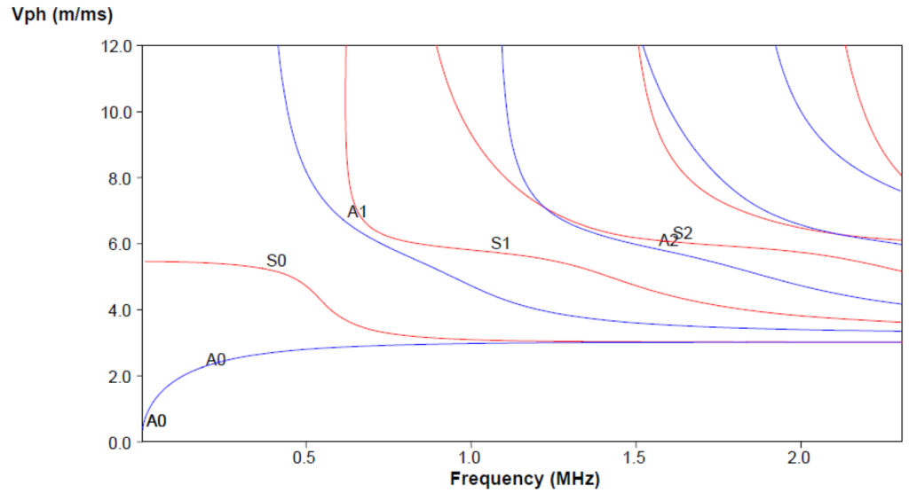
A Raleigh wave is a type of surface acoustic wave that propagates along a single surface of a very thick plate. A Lamb wave will behave like, and approach the velocity of, a Rayleigh wave when its wavelength becomes much smaller than the plate thickness. Rayleigh waves cannot inject acoustic energy into the fluid because this type of wave propagation limits particle displacement to only the outer surface of the pipe wall. For this reason, utilizing a Lamb wave sensor with the incorrect frequency for a given pipe (i.e., a pipe with a wall thickness much greater than one wavelength) will result in a significant reduction of the fluid signal amplitude, while also increasing the amplitude of the undesirable pipe wall signal.
In addition to reducing signal amplitude, operation of a Lamb wave sensor too far from the ideal pipe wall frequency will also lead to an increase in flow error (shown in Figure 3). This is primarily due to the fixed phase velocity of the sensor, which is defined by its wedge angle and sound speed.
A worthwhile endeavor
While some producers of clamp-on ultrasonic flow meters may feel that they are making a wise financial decision and doing customers a favor by limiting their available selection of Lamb wave sensors, scientific observation would argue to the contrary. Careful study of Lamb wave propagation has demonstrated a crucial fact: the likelihood of flow measurement error increases substantially if the frequency broadcast by a Lamb wave sensor is not well matched to the resonant frequency of the pipe wall. In the end, selecting the best possible sensor for a specific flow application will prove well worth the effort – for both the supplier and the end user.
Source of Article